
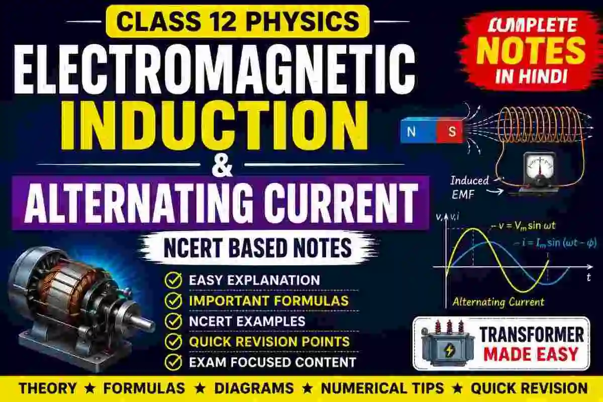
Class 12 Physics में Electromagnetic Induction and Alternating Current एक बहुत ही महत्वपूर्ण और scoring topic है। इस chapter से Board Exam तथा विभिन्न competitive exams में theory, numerical और conceptual questions पूछे जाते हैं। अगर आप विद्युतचुंबकीय प्रेरण (Electromagnetic Induction) और प्रत्यावर्ती धारा (Alternating Current) को आसान भाषा में समझना चाहते हैं, तो ये NCERT आधारित notes आपके लिए बहुत उपयोगी हैं। Download NCERT BOOK PDF.
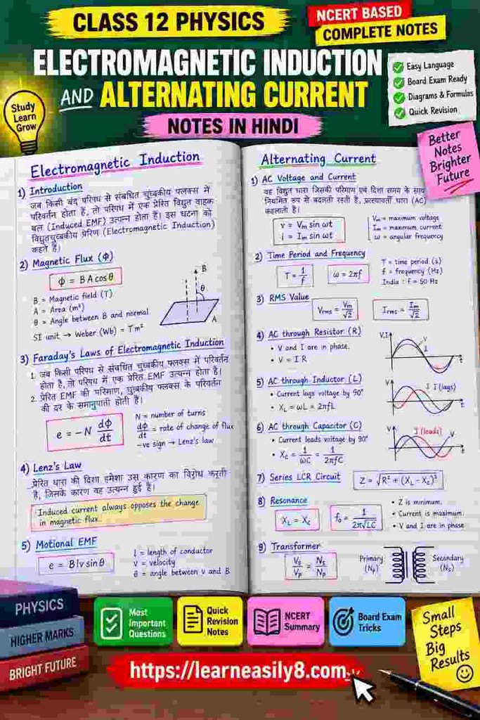
इन notes में Magnetic Flux, Faraday’s Laws, Lenz’s Law, Motional EMF, Self Induction, Mutual Induction, Eddy Currents, AC, RMS Value, Inductive Reactance, Capacitive Reactance, LCR Circuit, Resonance, Power Factor और Transformer जैसे सभी महत्वपूर्ण topics को Hindi + English में सरल तरीके से समझाया गया है। प्रत्येक concept को आसान definitions, महत्वपूर्ण formulas और quick revision points के साथ तैयार किया गया है, जिससे students को chapter समझने और परीक्षा से पहले तेजी से revision करने में मदद मिलेगी।
Electromagnetic Induction and Alternating Current Class 12: NCERT Physics Notes
Part A: Electromagnetic Induction
1. Introduction to Electromagnetic Induction (विद्युतचुंबकीय प्रेरण)
Electromagnetic Induction वह phenomenon है जिसमें किसी conductor या coil से जुड़ा magnetic flux बदलने पर EMF उत्पन्न होता है। यदि circuit closed हो, तो induced current भी flow करने लगता है। इस phenomenon की खोज Michael Faraday ने की थी। आधुनिक generators, transformers, induction cookers और कई electrical devices इसी principle पर काम करते हैं। मुख्य बात यह है कि केवल magnetic field होना पर्याप्त नहीं है; magnetic flux में परिवर्तन होना जरूरी है।
2. Magnetic Flux (चुंबकीय फ्लक्स)
Magnetic Flux किसी surface से गुजरने वाली magnetic field का माप है। इसे Greek letter Φ (Phi) से दर्शाया जाता है। यदि magnetic field uniform हो, तो magnetic flux का सूत्र होता है:
Φ = B A cos θ
जहाँ B = magnetic field, A = area और θ = magnetic field तथा area vector के बीच का angle है। इसका SI unit weber (Wb) है। Flux बदलने पर electromagnetic induction उत्पन्न हो सकता है।
3. Factors Affecting Magnetic Flux
Magnetic flux मुख्य रूप से तीन चीजों पर निर्भर करता है—magnetic field की strength, surface area और magnetic field तथा surface के बीच angle। यदि magnetic field बढ़े या area बढ़े, तो flux बढ़ सकता है। जब magnetic field surface के perpendicular होती है, flux maximum होता है। जब field surface के parallel होती है, flux zero होता है। इसलिए electromagnetic induction के लिए B, A या angle में परिवर्तन करके flux बदला जा सकता है।
4. What is Induced EMF? (प्रेरित विद्युत वाहक बल)
जब किसी coil से जुड़ा magnetic flux बदलता है, तो coil में उत्पन्न होने वाले EMF को Induced EMF कहते हैं। यह EMF किसी external battery के बिना उत्पन्न हो सकता है। यदि coil का circuit बंद हो, तो induced EMF के कारण induced current flow करता है। इसका direction हमेशा ऐसा होता है कि वह magnetic flux में होने वाले परिवर्तन का विरोध करता है। यही Lenz’s Law का मुख्य विचार है।
5. Faraday’s First Law of Electromagnetic Induction
Faraday का पहला नियम कहता है कि:
Whenever the magnetic flux linked with a circuit changes, an EMF is induced in the circuit.
अर्थात किसी coil या circuit से जुड़े magnetic flux में परिवर्तन होने पर उसमें induced EMF उत्पन्न होता है। यदि circuit closed हो, तो induced current भी उत्पन्न होता है। Magnetic flux में परिवर्तन magnet को coil के पास लाकर, दूर ले जाकर, magnetic field बदलकर या coil की position बदलकर किया जा सकता है।
6. Faraday’s Second Law of Electromagnetic Induction
Faraday का दूसरा नियम induced EMF की magnitude बताता है। इसके अनुसार induced EMF, magnetic flux के परिवर्तन की rate के proportional होता है।
e = -dΦ/dt
यदि coil में N turns हों:
e = -N(dΦ/dt)
Negative sign Lenz’s Law को दर्शाता है। इसका अर्थ है कि induced EMF की दिशा flux के परिवर्तन का विरोध करती है। Flux जितनी तेजी से बदलेगा, induced EMF उतना अधिक होगा।
7. Lenz’s Law (लेन्ज का नियम)
Lenz’s Law induced current की direction निर्धारित करता है। इसके अनुसार induced current की दिशा हमेशा ऐसी होती है कि वह उस कारण का विरोध करता है जिसके कारण वह उत्पन्न हुआ है। उदाहरण के लिए, यदि coil के पास आने से magnetic flux बढ़ रहा है, तो induced current ऐसा magnetic field बनाएगा जो इस वृद्धि का विरोध करे। यह law law of conservation of energy के अनुरूप है।
8. Why is There a Negative Sign in Faraday’s Law?
Faraday’s Law में negative sign:
e = -N(dΦ/dt)
Lenz’s Law को represent करता है। यह बताता है कि induced EMF और induced current की direction हमेशा magnetic flux में होने वाले परिवर्तन का विरोध करती है। यदि यह opposition नहीं होता, तो बिना external energy के लगातार energy उत्पन्न हो सकती थी, जो conservation of energy के विरुद्ध होता। इसलिए negative sign physical importance रखता है।
9. Ways to Produce Electromagnetic Induction
Electromagnetic induction कई तरीकों से उत्पन्न किया जा सकता है:
- Magnet को coil के पास या दूर ले जाकर।
- Coil को magnetic field में move करके।
- Magnetic field की strength बदलकर।
- Coil का area बदलकर।
- Coil को rotate करके।
- Magnetic field और coil के बीच angle बदलकर।
इन सभी स्थितियों में magnetic flux बदलता है। इसलिए induced EMF उत्पन्न होता है। मुख्य condition हमेशा यही है कि magnetic flux must change।
10. Motional EMF (गतिज प्रेरित EMF)
जब कोई conductor magnetic field में motion करता है और magnetic field lines को cut करता है, तो उसमें EMF induced होता है। इसे Motional EMF कहते हैं। इसका कारण conductor के free charges पर magnetic force लगना है। Charges अलग-अलग ends पर जमा हो जाते हैं और potential difference उत्पन्न होता है। यह principle electric generators और कई electromagnetic devices में उपयोग किया जाता है।
11. Formula for Motional EMF
यदि length l का conductor velocity v से magnetic field B में move कर रहा है, तो induced EMF:
e = Blv sin θ
जहाँ θ velocity और magnetic field के बीच angle है। जब conductor magnetic field के perpendicular move करता है:
e = Blv
इस स्थिति में induced EMF maximum होता है। यदि conductor magnetic field के parallel move करे, तो magnetic force zero होती है और induced EMF उत्पन्न नहीं होता।
12. Fleming’s Right-Hand Rule
Fleming’s Right-Hand Rule generator action में induced current की direction ज्ञात करने के लिए प्रयोग किया जाता है। अपने right hand की thumb, forefinger और middle finger को mutually perpendicular रखें।
- Forefinger → Magnetic Field
- Thumb → Motion of conductor
- Middle finger → Induced Current
यह rule electromagnetic generators और motional EMF से संबंधित numerical तथा conceptual questions में बहुत उपयोगी है।
13. Induced Current (प्रेरित धारा)
जब induced EMF किसी closed circuit में उत्पन्न होता है, तो circuit में flow होने वाली current को Induced Current कहते हैं। इसका magnitude circuit के resistance और induced EMF पर निर्भर करता है।
Ohm’s Law के अनुसार:
I = e/R
जहाँ I induced current, e induced EMF और R circuit का resistance है। Circuit open होने पर EMF उत्पन्न हो सकता है, लेकिन continuous current flow नहीं करेगा।
14. Self Induction (स्वप्रेरण)
Self Induction वह phenomenon है जिसमें किसी coil में current बदलने पर उसी coil में induced EMF उत्पन्न होता है। Current बदलने से coil द्वारा उत्पन्न magnetic field और magnetic flux बदलता है। यह changing flux उसी coil में induced EMF पैदा करता है। इस induced EMF की direction current में होने वाले परिवर्तन का विरोध करती है। इसे self-induced EMF भी कहते हैं।
15. Self Inductance (स्वप्रेरकत्व)
किसी coil की वह property जिसके कारण changing current अपने ही circuit में induced EMF उत्पन्न करता है, Self Inductance कहलाती है। इसे L से दर्शाते हैं।
Self-induced EMF:
e = -L (di/dt)
जहाँ L = self inductance और di/dt = rate of change of current। इसका SI unit henry (H) है। अधिक turns और suitable magnetic core होने पर inductance बढ़ सकती है।
Definition of One Henry
किसी coil की self inductance 1 henry होती है यदि उसमें current की rate of change 1 A/s होने पर coil में 1 volt का induced EMF उत्पन्न हो।
Mathematically:
1 H = 1 V s/A
Henry inductance की SI unit है। बड़े inductors electrical circuits में changing current को oppose करने के लिए उपयोग किए जाते हैं।
Factors Affecting Self Inductance
Self inductance मुख्य रूप से coil की structure और magnetic medium पर निर्भर करती है।
- Number of turns बढ़ने पर inductance बढ़ती है।
- Coil का area बढ़ने पर inductance बढ़ सकती है।
- Magnetic permeability बढ़ने पर inductance बढ़ती है।
- Coil की length बढ़ने पर inductance कम हो सकती है।
Soft iron core का उपयोग inductance बढ़ाने के लिए किया जाता है क्योंकि इसकी magnetic permeability अधिक होती है।
Mutual Induction (पारस्परिक प्रेरण)
जब एक coil में current बदलने के कारण पास स्थित दूसरी coil में EMF उत्पन्न होता है, तो इस phenomenon को Mutual Induction कहते हैं। पहली coil को primary और दूसरी coil को secondary कहा जा सकता है। Changing current primary coil का magnetic field बदलता है, जिससे secondary coil से जुड़ा magnetic flux बदलता है और उसमें induced EMF उत्पन्न होता है।
Mutual Inductance (पारस्परिक प्रेरकत्व)
दो coils के बीच changing current के कारण induced EMF उत्पन्न करने की क्षमता को Mutual Inductance कहते हैं। इसे M से दर्शाया जाता है।
Formula:
e = -M(di/dt)
जहाँ di/dt primary coil में current के परिवर्तन की rate है। Mutual inductance का SI unit भी henry (H) है। Transformer mutual induction के principle पर काम करता है।
Energy Stored in an Inductor
जब किसी inductor में current बढ़ाया जाता है, तो induced EMF current के परिवर्तन का विरोध करता है। इसलिए external source को work करना पड़ता है। यह work magnetic field में energy के रूप में store हो जाता है।
Stored energy:
U = ½LI²
जहाँ L = inductance और I = current। यह formula capacitor की electrical energy formula के समान महत्वपूर्ण है और numerical problems में frequently पूछा जाता है।
Eddy Currents (भंवर धाराएँ)
जब किसी solid conductor को changing magnetic field में रखा जाता है, तो उसके अंदर closed loops में induced currents उत्पन्न हो सकते हैं। इन्हें Eddy Currents कहते हैं। ये currents conductor के अंदर घूमती हुई दिखाई देती हैं, इसलिए इन्हें भंवर धाराएँ कहा जाता है। इनके कारण heating effect उत्पन्न होता है। Eddy currents useful भी हो सकते हैं और energy loss भी पैदा कर सकते हैं।
Uses of Eddy Currents
Eddy currents के महत्वपूर्ण applications हैं:
- Induction furnace में heating।
- Electromagnetic braking system।
- Speedometers।
- Electric power meters।
- Induction cookers।
- Metal detectors।
कुछ devices में eddy currents उपयोगी होते हैं, जबकि transformers में unwanted heating पैदा कर सकते हैं। इसलिए transformer cores को laminated बनाया जाता है ताकि eddy current losses कम किए जा सकें।
23. How to Reduce Eddy Current Losses
Transformer और अन्य electrical machines में eddy currents unwanted heat पैदा करते हैं। इन्हें कम करने के लिए iron core को एक solid block की बजाय thin insulated sheets में बनाया जाता है। इसे lamination कहते हैं। Insulation current के बड़े loops बनने से रोकती है। इससे eddy current की magnitude और heat loss कम होता है। यह electrical machines की efficiency बढ़ाने में महत्वपूर्ण भूमिका निभाता है।
Part B: Alternating Current
Introduction to Alternating Current
Alternating Current या AC वह electric current है जिसकी magnitude और direction समय के साथ periodically बदलती रहती है। घरेलू बिजली supply सामान्यतः alternating current होती है। भारत में AC supply की frequency सामान्यतः 50 Hz होती है। इसका अर्थ है कि current एक second में 50 complete cycles करता है। AC generation और transmission long distances पर बहुत convenient और economical है।
Difference Between AC and DC
AC (Alternating Current) की magnitude और direction दोनों समय के साथ बदलते हैं। इसके विपरीत DC (Direct Current) सामान्यतः एक ही direction में flow करती है। Batteries DC प्रदान करती हैं, जबकि power stations से घरों तक AC supply भेजी जाती है। AC voltage को transformer की सहायता से आसानी से step-up या step-down किया जा सकता है। इसी कारण long-distance power transmission में AC बहुत उपयोगी है।
Alternating Voltage and Current Equations
Sinusoidal alternating voltage को लिखा जाता है:
v = Vm sin ωt
और alternating current:
i = Im sin ωt
जहाँ Vm और Im maximum या peak values हैं। ω angular frequency है और t time है। Sinusoidal AC सबसे common waveform है क्योंकि rotating generators naturally sinusoidal voltage produce करते हैं और इसका mathematical analysis भी comparatively आसान होता है।
Time Period and Frequency of AC
AC का Time Period (T) एक complete cycle पूरा करने में लगने वाला समय है। Frequency (f) एक second में होने वाले complete cycles की संख्या है।
Relation:
f = 1/T
Angular frequency:
ω = 2πf
भारत की standard AC frequency 50 Hz है। इसलिए angular frequency:
ω = 2π × 50 = 100π rad/s
यह relation AC numericals में बहुत महत्वपूर्ण है।
Peak Value of AC
Alternating voltage या current का maximum instantaneous value Peak Value कहलाता है। इसे voltage के लिए Vm और current के लिए Im लिखा जाता है। Sinusoidal waveform में positive और negative दोनों maximum values होती हैं। Peak value circuit के maximum voltage या current को दर्शाती है। घरेलू appliances पर सामान्यतः RMS value लिखी होती है, peak value नहीं।
RMS Value of Alternating Current
RMS का अर्थ है Root Mean Square। यह AC की effective value है और वही DC current बताती है जो समान resistance में समान heating effect उत्पन्न करे।
For sinusoidal AC:
Irms = Im/√2
Similarly:
Vrms = Vm/√2
अर्थात RMS value peak value की लगभग 0.707 times होती है। घरेलू voltage ratings RMS values के रूप में दी जाती हैं।
Mean Value of AC
एक complete cycle में sinusoidal AC का average value zero होता है क्योंकि positive और negative halves एक-दूसरे को cancel कर देते हैं। लेकिन half cycle के लिए mean value zero नहीं होती।
Sinusoidal current का average value half cycle में:
Iavg = 2Im/π
Mean value और RMS value अलग-अलग concepts हैं। Heating effect और practical electrical calculations में RMS value अधिक महत्वपूर्ण होती है।
AC Through Different Circuits
AC Through a Pure Resistor
यदि AC circuit में केवल resistance R हो, तो voltage और current same phase में होते हैं। इसका मतलब दोनों simultaneously zero और maximum values प्राप्त करते हैं।
Ohm’s Law:
V = IR
Current equation: i = Im sin ωt
और voltage भी उसी phase में बदलता है। Pure resistor में electrical energy heat के रूप में continuously dissipate होती है।
Phase Relation in a Resistive Circuit
Pure resistive AC circuit में current और voltage के बीच phase difference:
φ = 0
इसलिए:
Current and voltage are in phase.
जब voltage maximum होता है, current भी maximum होता है। जब voltage zero होता है, current भी zero होता है। Resistor electrical energy को store नहीं करता बल्कि उसे heat energy में convert करता है। इसलिए resistive circuits में average power consumption वास्तविक रूप से होती है।
AC Through a Pure Inductor
Pure inductive circuit में inductor changing current का विरोध करता है। Inductor में self-induced EMF उत्पन्न होता है, जो current के परिवर्तन को oppose करता है। इसलिए AC circuit में current voltage के पीछे रहता है।
Pure inductor के लिए:
Current lags voltage by 90° (π/2)
Inductor energy को magnetic field में temporarily store करता है और बाद में source को वापस दे सकता है।
Inductive Reactance
Inductor द्वारा AC के opposition को Inductive Reactance कहते हैं। इसे XL से दर्शाते हैं।
XL = ωL = 2πfL
जहाँ f frequency और L inductance है। Frequency बढ़ने पर inductive reactance बढ़ती है। इसलिए high-frequency AC को inductor अधिक oppose करता है। इसका SI unit ohm (Ω) है। DC के लिए steady state में frequency zero होने के कारण ideal inductor का reactance zero माना जा सकता है।
AC Through a Pure Capacitor
Capacitor AC circuit में लगातार charge और discharge होता है। Pure capacitive circuit में current और voltage के बीच phase difference होता है।
Current leads voltage by 90° (π/2).
Capacitor electrical energy को electric field में temporarily store करता है। AC supply में capacitor बार-बार energy store और release करता है। Ideal capacitor में average power consumption zero होता है।
Capacitive Reactance
Capacitor द्वारा AC के opposition को Capacitive Reactance कहते हैं। इसे XC से दर्शाते हैं।
XC = 1/(ωC) = 1/(2πfC)
Frequency बढ़ने पर capacitive reactance कम होती है। इसलिए capacitor high-frequency signals को relatively आसानी से allow करता है। इसका SI unit ohm (Ω) है। DC के लिए steady state में ideal capacitor open circuit की तरह behave करता है।
Important Difference Between XL and XC
Inductive reactance:
XL = 2πfL
यह frequency बढ़ने पर बढ़ती है।
Capacitive reactance:
XC = 1/(2πfC)
यह frequency बढ़ने पर कम होती है।
इसलिए inductor high-frequency AC को अधिक oppose करता है, जबकि capacitor low-frequency AC को अधिक oppose करता है। यही opposite behavior LCR circuits और resonance को समझने में बहुत महत्वपूर्ण है।
Series LCR Circuit
What is a Series LCR Circuit?
जब एक resistor (R), inductor (L) और capacitor (C) को series में AC source के साथ connect किया जाता है, तो इसे Series LCR Circuit कहते हैं। Series connection होने के कारण सभी components में current समान होता है। लेकिन resistor, inductor और capacitor के across voltage के phase relations अलग-अलग होते हैं। कुल opposition को impedance कहा जाता है।
Impedance of Series LCR Circuit
Series LCR circuit का total opposition Impedance (Z) कहलाता है।
Formula:
Z = √[R² + (XL – XC)²]
जहाँ XL inductive reactance और XC capacitive reactance है। Current:
I = V/Z
Impedance resistance और reactance दोनों के combined effect को दर्शाती है। Z का SI unit भी ohm है। Impedance जितनी अधिक होगी, circuit current उतना कम होगा।
Phase Angle in LCR Circuit
Series LCR circuit में voltage और current के बीच phase angle φ होता है।
tan φ = (XL – XC)/R
यदि XL > XC, circuit inductive होता है और current voltage से lag करता है। यदि XC > XL, circuit capacitive होता है और current voltage से lead करता है। यदि XL = XC, phase angle zero होता है और current तथा voltage in phase होते हैं।
Resonance in Series LCR Circuit
जब inductive reactance और capacitive reactance बराबर हो जाएँ:
XL = XC
तो circuit resonance की स्थिति में होता है। इस समय impedance minimum होता है:
Z = R
और current maximum हो जाता है। Resonance पर voltage और current in phase होते हैं। Series LCR resonance radio tuning, communication systems और frequency selection में महत्वपूर्ण application रखता है।
Resonant Frequency
Resonance condition:
XL = XC
अर्थात:
ωL = 1/ωC
इससे resonant angular frequency:
ω₀ = 1/√LC
और resonant frequency:
f₀ = 1/(2π√LC)
Resonant frequency केवल L और C की values पर निर्भर करती है। Resistance resonance frequency को directly determine नहीं करता, लेकिन circuit response और sharpness को प्रभावित कर सकता है।
Power in AC Circuit
Instantaneous Power
किसी AC circuit में किसी particular instant पर consumed power को Instantaneous Power कहते हैं।
p = vi
क्योंकि AC voltage और current समय के साथ बदलते रहते हैं, instantaneous power भी बदलती रहती है। Inductive और capacitive circuits में energy source और circuit components के बीच बार-बार exchange होती है। इसलिए average power और instantaneous power के concepts अलग-अलग समझना जरूरी है।
Average Power in AC Circuit
AC circuit में average power का formula है:
P = Vrms Irms cos φ
जहाँ cos φ को Power Factor कहते हैं। केवल resistive circuit में φ = 0 होता है और cos φ = 1। Pure inductive तथा pure capacitive circuits में phase difference 90° होने से cos 90° = 0 होता है, इसलिए ideal condition में average power zero होती है।
Power Factor
Power Factor:
cos φ
है। यह बताता है कि supplied electrical power का कितना भाग useful average power में convert हो रहा है। Pure resistor में power factor 1 होता है। Pure inductor और pure capacitor में power factor zero होता है। Practical electrical systems में high power factor desirable होता है क्योंकि इससे energy transmission अधिक efficient हो सकती है।
Transformer
Introduction to Transformer
Transformer एक electrical device है जो AC voltage को increase या decrease करने के लिए उपयोग किया जाता है। यह mutual induction के principle पर काम करता है। इसमें primary और secondary coils तथा laminated soft iron core होता है। Transformer केवल changing magnetic flux के साथ प्रभावी रूप से काम करता है, इसलिए सामान्य transformer DC supply पर काम नहीं करता।
Principle of Transformer
Transformer का principle Mutual Induction है। Primary coil में alternating current flow करने पर changing magnetic field उत्पन्न होता है। यह magnetic flux iron core के माध्यम से secondary coil से link होता है। Changing flux के कारण secondary coil में induced EMF उत्पन्न होता है। Turns ratio के आधार पर secondary voltage primary voltage से अधिक या कम हो सकता है।
Construction of Transformer
Transformer के मुख्य भाग हैं:
- Primary coil
- Secondary coil
- Laminated soft iron core
Primary coil input AC supply से connected होती है। Secondary coil output प्रदान करती है। Soft iron core magnetic flux को efficiently guide करता है। Core को laminated बनाया जाता है ताकि eddy current losses कम हों। दोनों coils electrically isolated हो सकती हैं लेकिन magnetically coupled रहती हैं।
Transformer Turns Ratio
Ideal transformer के लिए:
Vs/Vp = Ns/Np
जहाँ Vs = secondary voltage, Vp = primary voltage, Ns = secondary turns और Np = primary turns।
यदि secondary coil में turns अधिक हों, voltage बढ़ता है। यदि secondary turns कम हों, voltage कम हो जाता है। यह equation transformer के सबसे महत्वपूर्ण formulas में से एक है।
Step-Up Transformer
जब secondary coil में turns की संख्या primary coil से अधिक होती है:
Ns > Np
तो:
Vs > Vp
ऐसे transformer को Step-Up Transformer कहते हैं। यह voltage बढ़ाता है और ideal condition में current कम करता है। Power stations में transmission के लिए voltage बढ़ाने हेतु step-up transformers उपयोग किए जाते हैं, जिससे transmission losses कम किए जा सकते हैं।
Step-Down Transformer
जब secondary coil में turns की संख्या primary coil से कम होती है:
Ns < Np
तो:
Vs < Vp
ऐसे transformer को Step-Down Transformer कहते हैं। यह high voltage को lower voltage में convert करता है। घरेलू electrical supply systems और electronic devices में suitable voltage प्राप्त करने के लिए step-down transformers उपयोग किए जाते हैं।
Transformer and Conservation of Energy
Ideal transformer में input power और output power लगभग समान मानी जाती है:
VpIp = VsIs
इसलिए यदि transformer voltage बढ़ाता है, तो current proportionally कम हो जाता है। इसी प्रकार voltage कम करने पर current बढ़ सकता है। Real transformers में कुछ energy heat और other losses के रूप में dissipate होती है, इसलिए efficiency 100% नहीं होती।
Losses in a Transformer
Transformer में मुख्य losses हैं:
- Copper loss due to resistance of coils।
- Eddy current loss in iron core।
- Hysteresis loss।
- Magnetic flux leakage।
इन losses को कम करने के लिए low-resistance copper wires, laminated cores और suitable magnetic materials का उपयोग किया जाता है। Transformer की अच्छी design electrical energy losses कम करके efficiency बढ़ाती है।
Why Transformer Does Not Work on DC?
Transformer को काम करने के लिए changing magnetic flux की आवश्यकता होती है। AC continuously changing current और magnetic field produce करता है, जिससे secondary coil में EMF induce होता है। DC steady current प्रदान करता है, इसलिए steady magnetic flux बनने के बाद secondary coil में continuous induced EMF नहीं बनता। इसलिए सामान्य transformer DC supply पर effectively काम नहीं करता।
Know More: Faraday’s Law of Electrolysis Class 12 Chemistry: Notes, Formula & PDF in Hindi
Important Differences
Difference Between Electromagnetic Induction and Self Induction
Electromagnetic Induction एक general phenomenon है जिसमें changing magnetic flux के कारण EMF उत्पन्न होता है। Self Induction में changing current उसी coil में changing magnetic flux उत्पन्न करता है और उसी coil में EMF induce करता है। Mutual Induction में एक coil का changing current दूसरी coil में EMF उत्पन्न करता है। इसलिए self और mutual induction electromagnetic induction के विशेष applications हैं।
Difference Between Inductor and Capacitor in AC
Inductor changing current का विरोध करता है और current voltage से 90° lag करता है। Capacitor changing voltage के कारण charge-discharge करता है और current voltage से 90° lead करता है। Inductive reactance frequency के साथ बढ़ती है, जबकि capacitive reactance frequency के साथ कम होती है। दोनों ideal components average power consume नहीं करते बल्कि energy temporarily store करके वापस source को देते हैं।
Important Formula Revision
Electromagnetic Induction Formula Sheet
Magnetic Flux
Φ = BA cos θ
Faraday’s Law
e = -N(dΦ/dt)
Motional EMF
e = Blv sin θ
Self-Induced EMF
e = -L(di/dt)
Mutual Induction
e = -M(di/dt)
Energy Stored in Inductor
U = ½LI²
इन formulas को units और physical meaning के साथ याद करना numerical problems के लिए बहुत उपयोगी है।
Alternating Current Formula Sheet
AC Voltage
v = Vm sin ωt
AC Current
i = Im sin ωt
Frequency
f = 1/T
Angular Frequency
ω = 2πf
RMS Values
Vrms = Vm/√2
Irms = Im/√2
ये formulas AC waveform और basic numerical questions के लिए सबसे महत्वपूर्ण हैं।
Reactance and LCR Circuit Formula Sheet
Inductive Reactance
XL = ωL = 2πfL
Capacitive Reactance
XC = 1/ωC = 1/(2πfC)
Impedance
Z = √[R² + (XL – XC)²]
Current
I = V/Z
Phase Angle
tan φ = (XL – XC)/R
इन equations से LCR circuit की complete behavior को समझा जा सकता है।
Resonance and Power Formula Sheet
Resonance Condition
XL = XC
Resonant Angular Frequency
ω₀ = 1/√LC
Resonant Frequency
f₀ = 1/(2π√LC)
Average Power
P = Vrms Irms cos φ
Power Factor
Power Factor = cos φ
Resonance पर impedance minimum और current maximum होता है। Power factor practical AC circuits की efficiency को समझने के लिए महत्वपूर्ण है।
Transformer Formula Sheet
Voltage Ratio
Vs/Vp = Ns/Np
Ideal Transformer Power
VpIp = VsIs
Step-Up Transformer
Ns > Np → Vs > Vp
Step-Down Transformer
Ns < Np → Vs < Vp
Transformer questions में turns ratio, voltage ratio और power conservation सबसे अधिक उपयोग किए जाने वाले concepts हैं।
Quick Revision Points
One-Minute Revision: Electromagnetic Induction
- Changing magnetic flux produces induced EMF.
- Faraday’s law gives magnitude of induced EMF.
- Lenz’s law gives direction.
- Negative sign represents opposition to change.
- Motional EMF: Blv sin θ
- Self induction occurs in same coil.
- Mutual induction occurs between two coils.
- Inductor stores energy: ½LI²
- Eddy currents are circulating induced currents.
- Transformer works on mutual induction.
One-Minute Revision: Alternating Current
- AC changes magnitude and direction periodically.
- India uses 50 Hz AC supply.
- RMS value = Peak value/√2.
- Resistor: V and I in phase.
- Inductor: I lags V by 90°.
- Capacitor: I leads V by 90°.
- XL increases with frequency.
- XC decreases with frequency.
- Resonance: XL = XC.
- AC power: P = VrmsIrms cos φ.
Most Important NCERT-Based Questions
Very Important Conceptual Questions
- What is electromagnetic induction?
- State Faraday’s laws of electromagnetic induction.
- Explain Lenz’s law.
- Why does Faraday’s law contain a negative sign?
- Define self inductance and mutual inductance.
- What are eddy currents?
- Define RMS value of AC.
- Explain inductive and capacitive reactance.
- What is resonance in LCR circuit?
- Why does a transformer not work on DC?
इन questions के answers concepts और formulas को जोड़कर लिखने चाहिए।
Electromagnetic Induction and Alternating Current – Important Numericals
Below are important exam-oriented numericals from Electromagnetic Induction and Alternating Current, explained step-by-step in simple language.
Part A: Electromagnetic Induction Numericals
Numerical 1: Magnetic Flux
A magnetic field of 0.5 T passes normally through a coil of area 0.2 m². Find the magnetic flux.
Given:
- B = 0.5 T
- A = 0.2 m²
- θ = 0°
Formula:
Φ = BA cos θ
Solution:
Φ = 0.5 × 0.2 × cos 0°
Φ = 0.1 Wb
Answer:
Magnetic Flux = 0.1 Weber (Wb)
Numerical 2: Magnetic Flux at an Angle
A surface of area 0.4 m² is placed in a magnetic field of 2 T. The angle between magnetic field and area vector is 60°. Find the magnetic flux.
Formula:
Φ = BA cos θ
Solution:
Φ = 2 × 0.4 × cos 60°
Φ = 0.8 × 0.5
Answer:
Φ = 0.4 Wb
Numerical 3: Faraday’s Law
A coil of 100 turns experiences a change in magnetic flux from 0.05 Wb to 0.01 Wb in 0.2 s. Find the induced EMF.
Given:
- N = 100
- ΔΦ = 0.05 − 0.01 = 0.04 Wb
- Δt = 0.2 s
Formula:
e = NΔΦ/Δt
Solution:
e = (100 × 0.04)/0.2
e = 20 V
Answer:
Induced EMF = 20 V
Numerical 4: Motional EMF
A conductor of length 2 m moves with velocity 5 m/s perpendicular to a magnetic field of 0.4 T. Find the induced EMF.
Formula:
e = Blv
Solution:
e = 0.4 × 2 × 5
e = 4 V
Answer:
Induced EMF = 4 Volt
Numerical 5: Motional EMF at an Angle
A conductor of length 1 m moves with velocity 10 m/s in a magnetic field of 0.5 T. The angle between velocity and magnetic field is 30°. Find induced EMF.
Formula:
e = Blv sin θ
Solution:
e = 0.5 × 1 × 10 × sin 30°
e = 5 × 0.5
Answer:
e = 2.5 V
Numerical 6: Self Inductance
The current in an inductor changes from 2 A to 8 A in 3 seconds. The induced EMF is 4 V. Find the self-inductance.
Formula:
e = L(di/dt)
Therefore:
L = e × dt/di
Solution:
L = (4 × 3)/(8 − 2)
L = 12/6
Answer:
L = 2 Henry
Numerical 7: Energy Stored in an Inductor
An inductor of inductance 4 H carries a current of 3 A. Find the energy stored.
Formula:
U = ½LI²
Solution:
U = ½ × 4 × (3)²
U = 2 × 9
Answer:
U = 18 Joule
Part B: Alternating Current Numericals
Numerical 8: RMS Value of Current
The peak current in an AC circuit is 10 A. Find the RMS current.
Formula:
Irms = Im/√2
Solution:
Irms = 10/√2
Irms = 7.07 A
Answer:
RMS Current = 7.07 A
Numerical 9: Peak Voltage
The RMS voltage of an AC supply is 220 V. Find the peak voltage.
Formula:
Vm = √2 Vrms
Solution:
Vm = 1.414 × 220
Answer:
Vm ≈ 311 V
Numerical 10: Frequency and Time Period
An AC supply has a frequency of 50 Hz. Find its time period.
Formula:
T = 1/f
Solution:
T = 1/50
T = 0.02 second
Answer:
Time Period = 0.02 s
Numerical 11: Angular Frequency
Find the angular frequency of an AC supply having frequency 50 Hz.
Formula:
ω = 2πf
Solution:
ω = 2π × 50
Answer:
ω = 100π rad/s ≈ 314 rad/s
Numerical 12: Inductive Reactance
An inductor of inductance 0.2 H is connected to an AC supply of frequency 50 Hz. Find its inductive reactance.
Formula:
XL = 2πfL
Solution:
XL = 2π × 50 × 0.2
XL = 62.8 Ω
Answer:
Inductive Reactance = 62.8 Ω
Numerical 13: Capacitive Reactance
A capacitor of capacitance 100 μF is connected to an AC supply of frequency 50 Hz. Find the capacitive reactance.
Given:
C = 100 μF = 100 × 10⁻⁶ F
Formula:
XC = 1/(2πfC)
Solution:
XC = 1/(2π × 50 × 100 × 10⁻⁶)
Answer:
XC ≈ 31.8 Ω
Numerical 14: AC Through a Resistor
A resistor of 20 Ω is connected to a 200 V RMS AC supply. Find the RMS current.
Formula:
I = V/R
Solution:
I = 200/20
Answer:
I = 10 A
Part C: LCR Circuit Numericals
Numerical 15: Impedance of LCR Circuit
A series LCR circuit has:
- R = 10 Ω
- XL = 30 Ω
- XC = 20 Ω
Find the impedance.
Formula:
Z = √[R² + (XL − XC)²]
Solution:
Z = √[10² + (30 − 20)²]
Z = √(100 + 100)
Z = √200
Answer:
Z = 14.14 Ω
Numerical 16: Current in LCR Circuit
A series LCR circuit has impedance 20 Ω and RMS voltage 100 V. Find the RMS current.
Formula:
I = V/Z
Solution:
I = 100/20
Answer:
I = 5 A
Numerical 17: Resonant Frequency
An LCR circuit has:
- L = 0.1 H
- C = 10 μF
Find the resonant frequency.
Formula:
f₀ = 1/(2π√LC)
Solution:
C = 10 × 10⁻⁶ F
f₀ = 1/[2π√(0.1 × 10 × 10⁻⁶)]
Answer:
f₀ ≈ 159 Hz
Part D: Transformer Numericals
Numerical 18: Transformer Voltage
A transformer has:
- Primary turns = 500
- Secondary turns = 100
- Primary voltage = 220 V
Find the secondary voltage.
Formula:
Vs/Vp = Ns/Np
Solution:
Vs/220 = 100/500
Vs = 44 V
Answer:
Secondary Voltage = 44 V
Numerical 19: Step-Up Transformer
A transformer has 200 turns in the primary coil and 1000 turns in the secondary coil. The primary voltage is 20 V. Find the secondary voltage.
Formula:
Vs/Vp = Ns/Np
Solution:
Vs/20 = 1000/200
Vs = 20 × 5
Answer:
Vs = 100 V
Numerical 20: Transformer Current
An ideal transformer has:
- Primary voltage = 200 V
- Primary current = 2 A
- Secondary voltage = 50 V
Find the secondary current.
Formula:
VpIp = VsIs
Solution:
200 × 2 = 50 × Is
Is = 400/50
Answer:
Secondary Current = 8 A
Most Important Formulas for Numericals
Electromagnetic Induction
Φ = BA cos θ
e = -N(dΦ/dt)
e = Blv sin θ
e = -L(di/dt)
U = ½LI²
Alternating Current
Irms = Im/√2
Vrms = Vm/√2
T = 1/f
ω = 2πf
Reactance
XL = 2πfL
XC = 1/(2πfC)
LCR Circuit
Z = √[R² + (XL − XC)²]
I = V/Z
f₀ = 1/(2π√LC)
Transformer
Vs/Vp = Ns/Np
VpIp = VsIs
Exam Tips for Students
इस chapter में formulas को केवल याद न करें, बल्कि उनके physical meaning को समझें। पहले magnetic flux और Faraday’s Law मजबूत करें, फिर Lenz’s Law की direction practice करें। AC chapter में phase difference और reactance सबसे महत्वपूर्ण topics हैं। LCR circuit के formulas को एक साथ revise करें। Transformer के turns ratio तथा resonance के numerical questions बार-बार practice करें। Diagram और phase relation लिखने से answers अधिक effective बनते हैं।
Conclusion
Electromagnetic Induction and Alternating Current Class 12 Physics का अत्यंत महत्वपूर्ण chapter combination है। Electromagnetic induction हमें बताता है कि changing magnetic flux से EMF कैसे उत्पन्न होता है, जबकि alternating current electrical power systems की practical working को समझाता है। Faraday’s Law, Lenz’s Law, inductance, AC circuits, reactance, resonance और transformer इस topic के मुख्य pillars हैं। इन concepts और formulas की नियमित revision से board examinations और competitive exams दोनों में अच्छे marks प्राप्त किए जा सकते हैं।